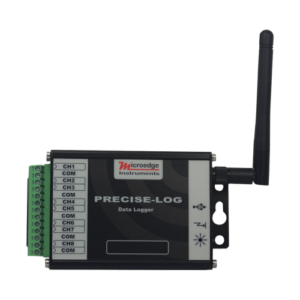
Descripción
Producto: Registrador de datos de voltaje inalámbrico
Hecho por: MICROEDGE INSTRUMENTS (CANADA)
Serie: PRECISE-LOG
Modelo: PL-VW
PL-VW es un registrador de datos de voltaje de 8 canales, alimentado por batería, independiente y habilitado para WIFI. El registrador registra ocho fuentes de voltaje externas y guarda datos en la memoria de 8 MB.
Su carcasa de aluminio lo hace excelente en el entorno industrial más duro.
El módulo WIFI incorporado permite la monitorización y descarga remota de datos.
El ADC de 16 bits lo hace muy adecuado para aplicaciones científicas y de laboratorio donde las mediciones precisas y precisas son críticas.
Simplemente encienda el registrador en el área cubierta WIFI y acceda a él desde su computadora para la configuración, descarga, visualización de gráficos y más ...
Caracteristicas:
- Convertidor analógico a digital de 16 bits
- Tamaño de memoria de 8 megabytes
- Comunicación USB y WIFI. Interfaces con velocidad de transmisión de 115200 bps
- Rangos de entrada programables (5 VDC, 20 VDC)
- Más de 10 años de duración de la batería.
- Potente software para configuración, descarga, trazado, análisis e informes de alarmas.
- Amplias selecciones de intervalo de muestreo (de un segundo a 12 horas)
- Caja de aluminio resistente.
Modbus
From July 15th, 2019, Modbus TCP protocol will be added to all PRECISE-LOG series of data loggers. A Modbus master/client can read one or more Input Registers and Holding Registers available in a PRECISE-LOG data logger through Modbus TCP communications. The below specifications list all supported commands and available registers PL-VW data logger supports:
Input Registers:
An Input Register stores a 16-bit integer for a channel’s real-time reading. To read one or more 16-bit Input register data, use function code 4.
| Register |
Description |
Type |
Range |
| 0 |
CH0 Value |
Unsigned Integer |
0 - 65535 |
| 1 |
CH1 Value |
Unsigned Integer |
0 - 65535 |
| 2 |
CH2 Value |
Unsigned Integer |
0 - 65535 |
| 3 |
CH3 Value |
Unsigned Integer |
0 - 65535 |
| 4 |
CH4 Value |
Unsigned Integer |
0 - 65535 |
| 5 |
CH5 Value |
Unsigned Integer |
0 - 65535 |
| 6 |
CH6 Value |
Unsigned Integer |
0 - 65535 |
| 7 |
CH7 Value |
Unsigned Integer |
0 - 65535 |
Example:
To read CH2, CH3 and CH4's real-time values, a Modbus master device sends in the following command:
| Data(HEX) |
Description |
Note |
| 0001 |
Transaction identifier |
Fixed 2-byte value |
| 0000 |
Protocol identifier |
Fixed 2-byte value |
| 0006 |
Length(6 bytes are followed) |
2-byte value |
| 01 |
The device address |
1-byte value, don't care |
| 04 |
Function Code (read Input Register) |
1-byte value |
| 0002 |
First register's address |
2-byte value |
| 0003 |
The number of required registers (read 3 registers 0002 to 0004) |
2-byte value |
Holding Registers:
A Holding Register stores a 16-bit integer indicating a setting for the data logger. To read one or more 16-bit Holding Register data, use function code 3.
| Register |
Description |
Type |
Range/Equation |
| 0 |
Sample Interval |
0: below 1 second
>=1: sample interval in second |
0 - 65535 seconds |
| 1 |
Device Operating Mode |
0: logging stopped
1: logger is logging data |
|
| X0 |
CHX-1 Type |
0: Range#0 (0 to 20 VDC)
1: Range#1 (0 to 5 VDC)
2: Range#2 (-5 to +5 VDC) |
|
| X1 |
CHX-1 Enabled |
0:disabled
1:enabled |
If a channel is disabled, the reading is unknown |
| X2 |
CHX-1 Equation |
0: Range#0 Voltage |
Range: 0 to 20 VDC
Equation
O = 20 * I / 65535 |
| 1: Range#1 Voltage |
Range: 0 to 5 VDC
Equation:
O = 5 * I / 65535 |
| 2: Range#2 Voltage |
Range: -5 to +5 VDC
Equation:
O = 10 * I / 65535 – 5 |
| 3: Linear |
O = (LRH – LRL) * I / 65535 + LRL
Where:
LRH is Linear Range high value
LRL is Linear Range low value
You can get those values from SiteView |
Where X = 1,2,3,4,5,6,7,8
O = Output, I = Input Register Value
Example:
To read CH3's equation, a Modbus master device sends in the following command:
| Data(HEX) |
Description |
Note |
| 0001 |
Transaction identifier |
Fixed 2-byte value |
| 0000 |
Protocol identifier |
Fixed 2-byte value |
| 0006 |
Length(6 bytes are followed) |
2-byte value |
| 01 |
The device address |
1-byte value, don't care |
| 03 |
Function Code (read Holding Register) |
1-byte value |
| 002A |
First register's address (42 is 2A in HEX) |
2-byte value |
| 0001 |
The number of required registers (read 1 registers 002A) |
2-byte value |
Note:
- Modbus feature was added to firmware version 2.05 or above.To upgrade a data logger's firmware please refer to this link: How can I upgrade logger firmware?
- The age of an Input Register data is based the data logger's sample interval.If the logger has stopped logging or the logger's sampling interval is slower than five seconds, a request of Input Register data will initiate the sampling process and the new data will be available upon the next request.


